A Bluey Player for Kids
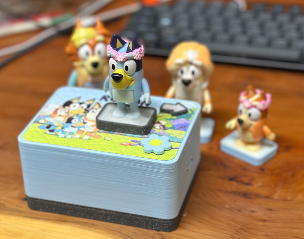
My son has a friend who's a big fan of Bluey, and loved listening to the Bluey book reads.
I'd previously made a simple Toniebox style player, using a Raspberry Pi Zero, wifi, and an NFC reader to play a mix of music, animal sounds, etc. The issue is that the RPi is running a whole Linux stack, and ensuring it would work reliably as a gift was not simple (try explaining to a three-year-old that the player has to 'boot up' for 30 seconds before working).
This time, I decided to use an rp2040 microcontroller so the whole unit could be simpler and more reliable.
The underlying concept is quite simple: The player has an internal (sd card) memory with all tracks pre-loaded, and an rfid reader. When a known tag is read, the UID of the tag is used as a key to find the right track to play, and then the track is played:
              [ RFID Chip ]
                   ~~~
                    |
              [ RFID Reader ]
                    |
                    |
[ SD Card ] ── [ RP2040 ] ── [ Amplifier ] ── [ Speaker ]
                 /      \        /
                /        \      /
       [ Buttons ]    [ Power/USB ]
To get this working, I needed to:
- Design the case/mechanical parts
- Build the electronics
- Write the player code
Mechanical Design
The Case
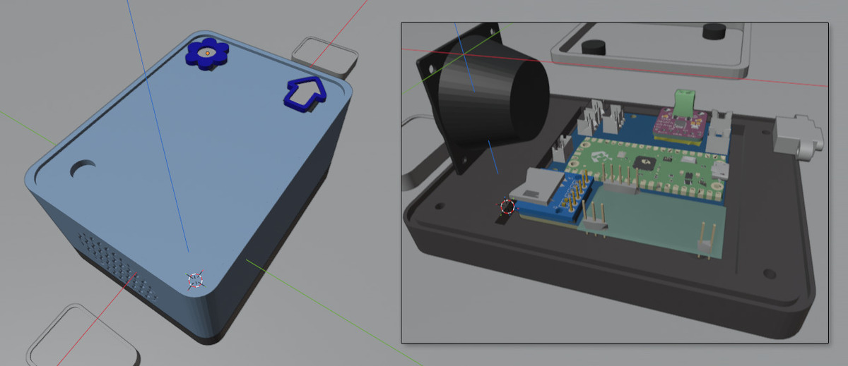
I've been 3d printing for a few years now, and the case ended up quite simple. It's basically a box with some holes for the parts.
With this design, I wanted to use magnets to stop the RFID 'tags' from being knocked off while playing, and to give a satisfying positive action when the tag is placed. From previous experience, I knew that having things loosely attached to a device that's playing music can make things buzz, so I decided to have a thin leather cover on the top of the box, so the tags would sit on soft leather rather than hard plastic.
This meant that the 3d printed box needed a large recessed area of a few mm for the leather to sit without exposing ragged edges. So the print had some large support areas, which is a bit of a pain. I also had to leave some holes for buttons and an LED* in the top, and a recessed area underneath for the RFID loop.
The speaker holes were designed with a simple wave pattern and some internal supports to give enough space for the sound to escape.
The base has an area for the circuit board, and basic pillar/hole design for screwing the case/speaker/usb together.
I use blender for most of my 3d modelling, and have developed a workflow that allows accurate modelling (despite Blender's reputation on this front). Despite spending a chunk of time modelling things in Fusion 360, I just feel more comfortable with Blender.
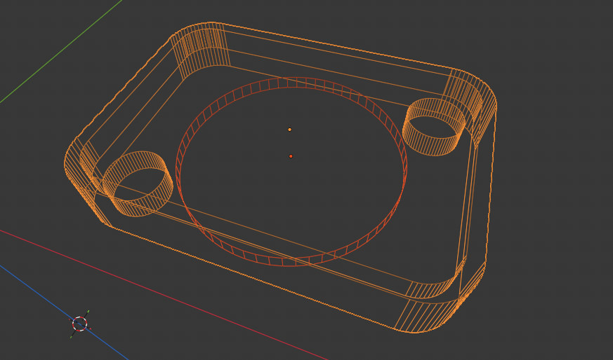
Typically NFC readers/tags use 13.56MHz to communicate. At this high frequency, the pickup coils tend to be quite small (usually printed onto a board). I wanted the reader to be centered under the tags, but also to allow magnetic positioning without interference. So instead, I chose to use the less-common 125khz RFID standard. These readers have nice large coils to drive a lower frequency field, and plenty of space for magnets to sit in the middle without significantly impacting the radio comms.
I decided that the player needed two buttons, one a play/pause button, and one a skip button. There were more book reads than I wanted to get characters for (and they'd have to store/keep them!) so each tag actually starts a playlist of stories, and pressing the skip button jumps to the next story.
The Tags
The NFC/RFID tags I use come as basic white plastic circular discs. They're thin, fiddly, and not very inspiring on their own, but they are also very easy to embed in a 3d print (combination of a PAUSE G-code, a quick dab of glue, place the tag and magnets, then continue). As this player is Bluey-themed, I wanted to have physical Bluey characters to place on the top, but also didn't want to fully print 3d characters, as this would not only take a really long time, but also the result would not be very smooth. Instead, I found a set of cheap Bluey plastic toys, designed/printed some bases they could stand in that had the tags, and then epoxied the toys to the base. This came out looking quite nice.
One major consideration was ensuring the tiny magnets were placed with the right polarity, so the tags snap into position, rather than being rejected by the base.
The Cover
There's a company in the UK that can print custom designs onto a wide variety of fabrics, including leather. The leather feels a bit synthetic (Described as Nappa full grain with stamped texture), probably because of how much they have to do to make a good print surface. For this purpose, it worked perfectly, adding a soft, durable and good looking surface for the tags. The design took some creative liberties with some official Bluey artwork (this is a non-commercial one-off!) and I added a 'landing zone' for the tags, so it was clear where to place them.
The Electronics
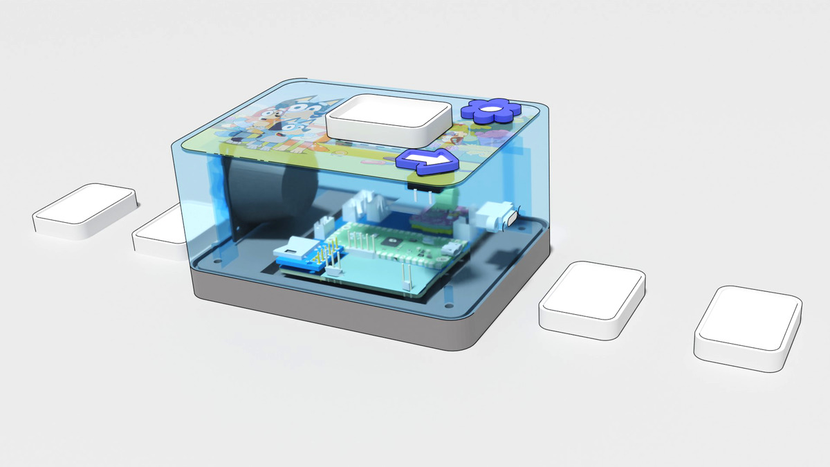
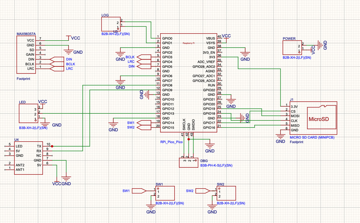
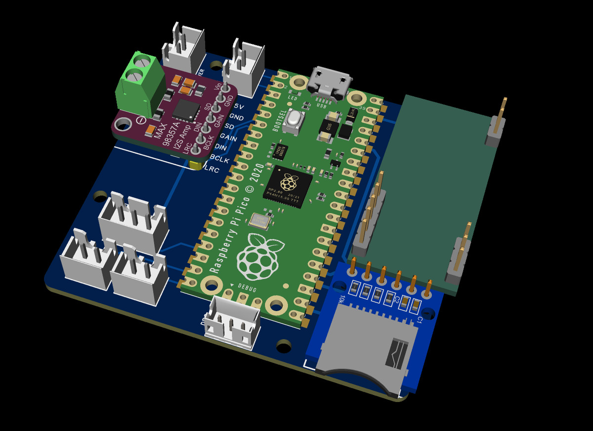
I cheated quite heavily with the electronics. Rather than design a single complete circuit, I designed a circuit board that could hold 4 pre-made modules: the rp2040 on a rp-pico board, a pre-soldered sd card slot, an rfid reader module and a small I²S amplifier. This meant that all the routing/soldering was just between larger modules, rather than trying to design a single circuit.
(Please forgive the poor practices here! Things would be neater these days)
And a simple compact 2-layer layout:
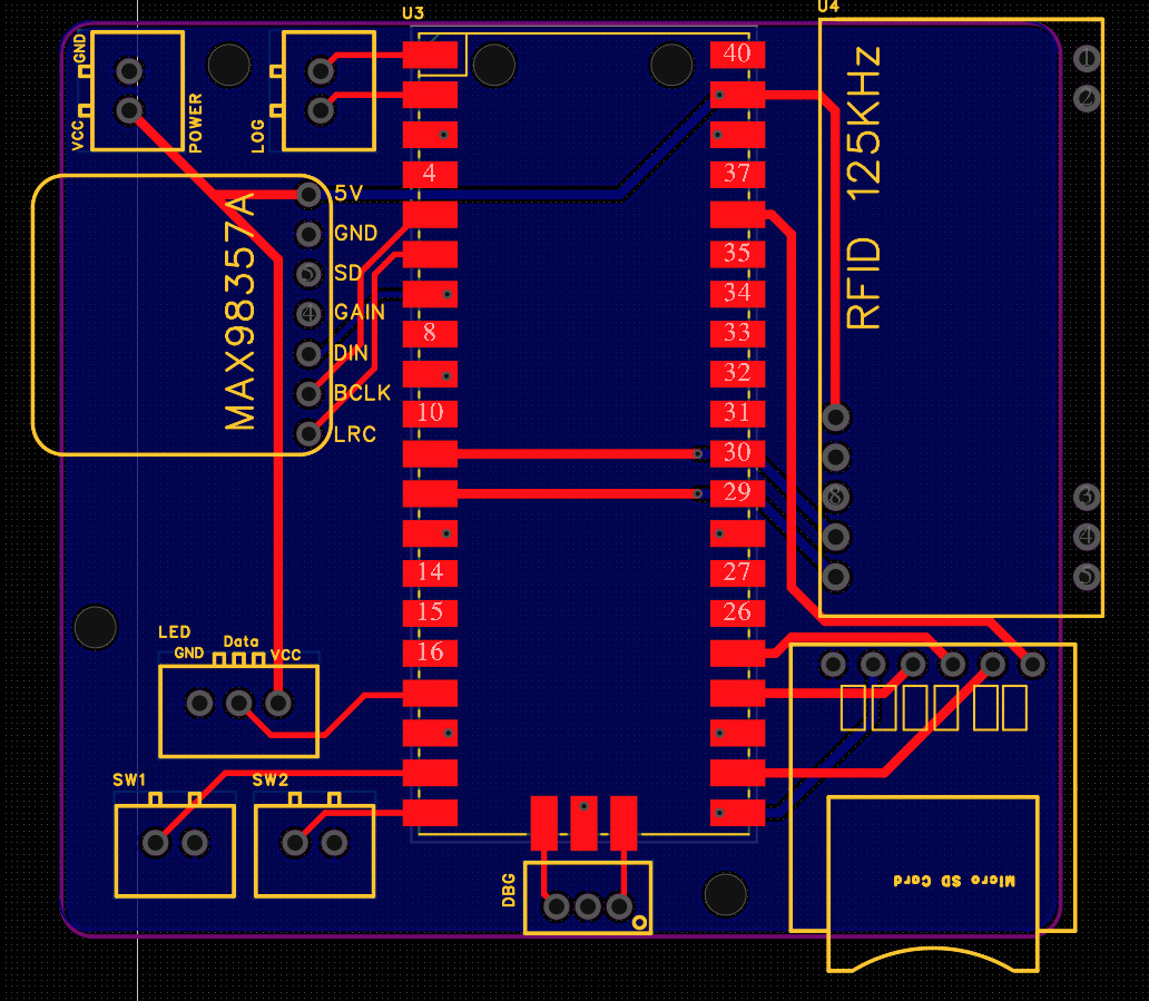
JLC PCB had them made up and delivered in a few weeks. The modules were acquired from a low-cost Chinese retailer, except the Pico, and all performed absolutely fine. Soldering was simple, as the pin spacing on all the modules was standard 2.54mm.
The Software
The repository <- Just the code, no sound or graphics files (copyright) or the 3d models (I can provide the 3d files if anyone wants)
My go-to stack for writing rp2040/2350 code is Rust with embassy. Over time it's got better and better, and managing concurrency using async makes many things much simpler.
In this case, I had to do quite a lot: interfacing with the RFID reader, streaming audio from the SD card, outputting I²S to the amp, and responding to button presses. The async model makes this much simpler, as each of these tasks can be written as a separate async task, and the embassy runtime handles scheduling them.
The main issue here was working out how to stream the sound between the sd card and the amp. Rust is very careful about memory safety, and the default approach would be to just copy each byte a bunch of times (as buffers) to read/process/enqueue the audio data. This is easy to do safely, but isn't very efficient.
Instead, I have a simple rp2040 PIO DMA driver that outputs I²S efficiently, and just has to be supplied with a buffer of audio data. When the player begins a track, the function that actually handles reading the file contents (after walking the FAT and error handling/lifecycle management) in the sd card task, requests temporary exclusive write ownership of a buffer, using an embassy zero-copy channel. The read end is connected to the DMA I²S output.
In order to comply with the PIO DMA alignment requirements, the actual buffer used is a carefully aligned static ring buffer implementation.
The main 'loop' is a shared EVENT (embassy mpsc) channel that anyone can publish to, and is consumed by a controller that then decides which state changes to transition to. Due to some issues with the LED*, the controller ended up just signalling the sd card task to start/stop/skip, all other events are handled locally by the tasks themselves.
The tasks:
 CORE 0                                      CORE 1
┌────────────────┐                          ┌─────────────┐
│                ◄──── EVENT_CHANNEL ───────┤ RFID reader │
│   Controller   │                          └─────────────┘
│                ├───── SD_CONTROL ───┐     ┌─────────────┐
└───────▲────────┘                    └─────► SD task     │
        │                                   │ Read audio  │
 EVENT_CHANNEL                              └──────┬──────┘
        │                                          │
┌───────┴─────┐                                    │
│ Button tasks│                                    │
│ Next / Play │                                    │
└─────────────┘                                    │
┌─────────────┐        audio buffers               │
│ I²S out     ◄─────── play-state signal ──────────┘
│ DMA playback│
└─────────────┘
The Sound Files
To avoid on-device complexity, the sound files (sourced as mp3 files) are pre-converted to raw 44.1 kHz 16-bit mono PCM data. This is then copied to the sd-card to be read over the SPI-based sd card interface (courtesy of the embedded_sdmmc crate).
I used OpenAI to generate pleasant-sounding voices to introduce the story title, and stitched each playlist together into one raw pcm file.
The amplifier I was using only supported stereo in, but I also only connected one speaker, so the I²S driver just output 0s to the right channel, filling the left channel with the mono audio.
Snags
Audio Filtering
One thing I hadn’t anticipated was the amount of switching noise produced by the Class-D I²S amplifier module. Spoken audio sounded crackly and unpleasant, but adding a makeshift inline LC filter on the speaker output resolved the problem.
*LED
Initially, I planned on having an sk6812 multi-colour LED on the top of the box, shining through the top cover, to indicate status etc. Unfortunately, when I put the LED into the final design, there was no sign of it. The LED is very bright, but the leather top was so opaque that there was no indication of it at all. Rather than have it taking up CPU/power and generating heat for no reason, I removed the LED and supporting code, relying on the device just working and the sound to indicate status.
The Result